在開始在ArduinoIDE上開發前,請先參考以下兩篇,如果已經熟悉可忽略
STM32duino-如何在ArduinoIDE使用STM32(新版)(以STM32F103為例)
STM32duino-如何在ArduinoIDE使用STM32(新版)(以STM32L475為例)
下方有程式碼,請自行複製貼上
請參照下方腳位說明:
PWM:
PA0,PA1, PA2, PA3, PA6, PA7, PA8, PA9, PA10, PB0, PB6, PB7
ADC:
PA0,PA1, PA2, PA3, PA4, PA5, PA6, PA7
TXRX:
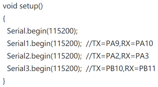
(這個的串口名稱是有規定不能隨意更改的,因為STM的溝通方式本來就不適用Arduino內建的Serial函式庫)
|
定義名稱 |
TX |
R |
|
Serial1 |
PA9 |
PA10 |
|
Serial2 |
PA2 |
PA3 |
|
Serial3 |
PB8 |
PB11 |
範例如下

I2C :(預設是默認使用I2C1也就是PB6,PB7,第二組需要另外再開啟)
|
SCL |
SDA |
|
PB6 |
PB7 |
|
PB10 |
PB11 |
該範例將使用TIM1產生兩個不同的計時器,週期為0.5跟1秒,可以從結果中推論出同樣做一樣的動作但週期的不同
累加數值的速度更快,而且從運行的數值發現是符合規律的
程式碼:
#include "STM32TimerInterrupt.h"
#include "STM32_ISR_Timer.h"
#define TIMER_INTERVAL_MS 100
#define HW_TIMER_INTERVAL_MS 50
int A = 0;
int B = 0;
int C = 0;
// Depending on the board, you can select STM32 Hardware Timer from TIM1-TIM22
// For example, F767ZI can select Timer from TIM1-TIM14
// If you select a Timer not correctly, you'll get a message from ci[ompiler
// 'TIMxx' was not declared in this scope; did you mean 'TIMyy'?
// Init STM32 timer TIM1
STM32Timer ITimer(TIM1);
// Init STM32_ISR_Timer// Each STM32_ISR_Timer can service 16 different ISR-based timers
STM32_ISR_Timer ISR_Timer;
#define TIMER_INTERVAL_0_5S 500L
#define TIMER_INTERVAL_1S 1000L
void TimerHandler()
{ISR_Timer.run();}
// In STM32, avoid doing something fancy in ISR, for example complex Serial.print with String() argument
// The pure simple Serial.prints here are just for demonstration and testing. Must be eliminate in working environment
// Or you can get this run-time error / crash
void doingSomething1()
{
A = A + 1;
}
void doingSomething2()
{
B = B + 1;
}
/*void doingSomething3()
{
digitalWrite(LED_RED, !digitalRead(LED_RED));
}*/
void setup()
{
Serial.begin(115200);
delay(100);
Serial.print(F("\nStarting TimerInterruptDemo on : "));
Serial.println(BOARD_NAME);
Serial.println(STM32_TIMER_INTERRUPT_VERSION);
Serial.print(F("CPU Frequency = "));
Serial.print(F_CPU / 1000000);
Serial.println(F(" MHz"));
// Instantiate HardwareTimer object. Thanks to 'new' instanciation, HardwareTimer is not destructed when setup() function is finished.
//HardwareTimer *MyTim = new HardwareTimer(Instance);
// Interval in microsecs
if (ITimer.attachInterruptInterval(HW_TIMER_INTERVAL_MS * 1000, TimerHandler))
{
Serial.print(F("Starting ITimer OK, millis() = ")); Serial.println(millis());
}
else
Serial.println(F("Can't set ITimer. Select another freq. or timer"));
// Just to demonstrate, don't use too many ISR Timers if not absolutely necessary
// You can use up to 16 timer for each ISR_Timer
ISR_Timer.setInterval(TIMER_INTERVAL_0_5S, doingSomething1);
ISR_Timer.setInterval(TIMER_INTERVAL_1S, doingSomething2);
}
void loop()
{
Serial.print("A:");
Serial.print(A);
Serial.print("B:");
Serial.println(B);
delay(100);
}
執行結果:


 留言列表
留言列表

